Create Flow Graph
Design the layout of your procedural dungeons using the flow editor. Then create an infinite number of procedural dungeons that follow this layout rule.
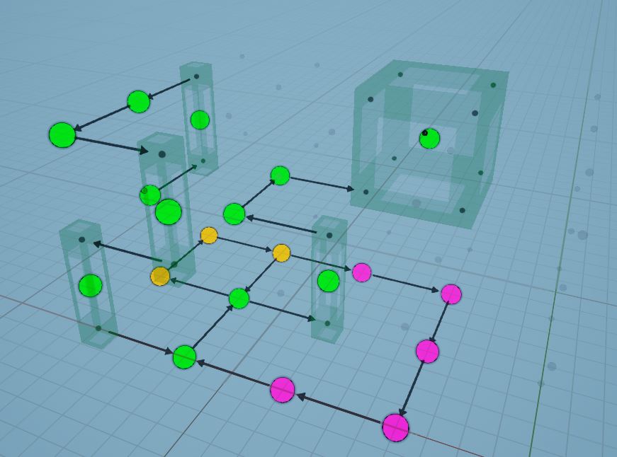
Create cyclic-paths, key-locks, teleporters, shops, treasure rooms, boss rooms and much more
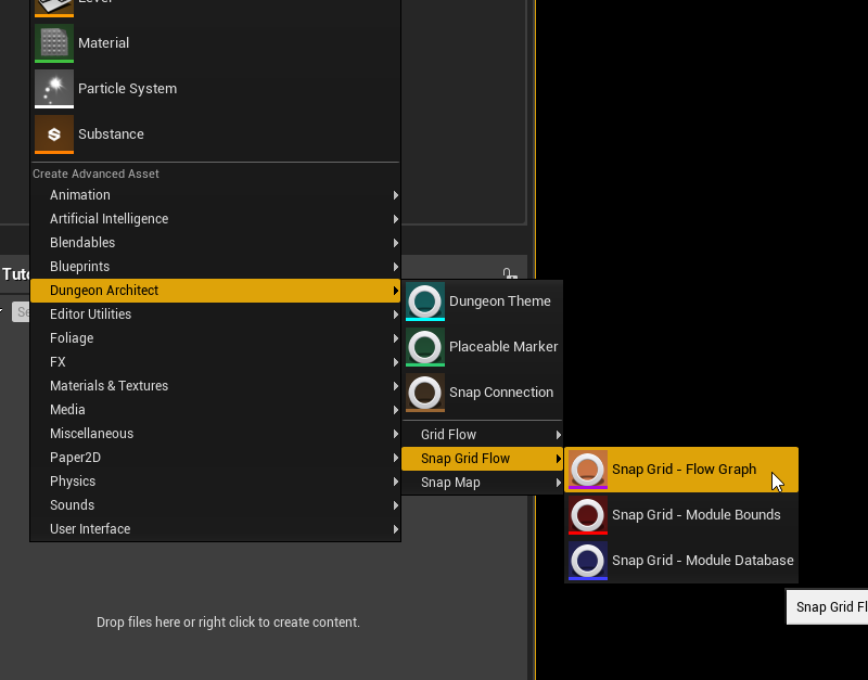
Create a Snap Grid Flow Asset
Right click on the Content Browser and choose Dungeon Architect > Snap Grid Flow > Snap Grid - Flow Graph

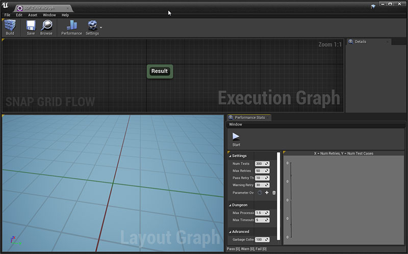
Double click the asset to open the Snap Grid Flow Editor
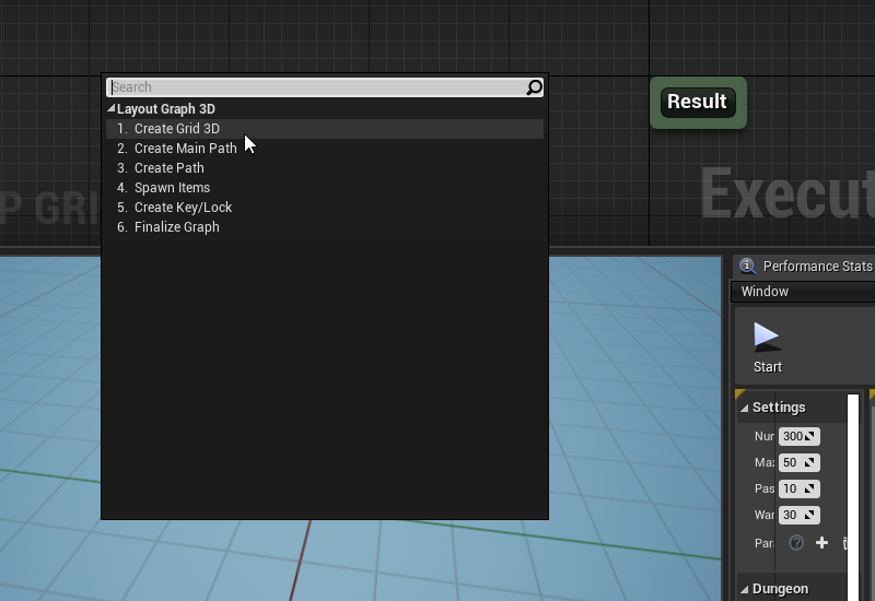
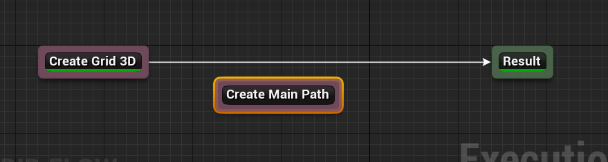
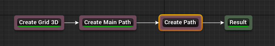
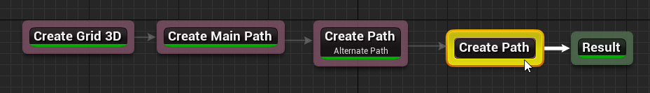
Right click on the Execution Graph and choose Create Grid 3D
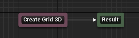
Link the Create Grid 3D node to the Result node
You connect two nodes together by hovering the mouse over the border of the node. When the border turns yellow, drag out a link and connect it to the other node's border.
Disconnect by holding the Alt key and left click on the border. This will break all outgoing links
Create Grid
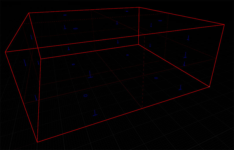
Select the Create Grid 3D node and have a look at the node's properties in the Details tab
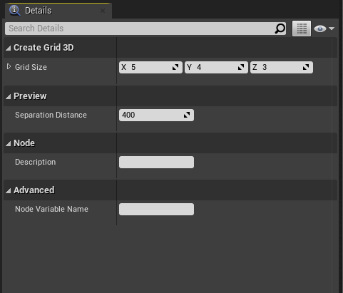
This node creates an initial working area for your flow graph to grow on. The Grid Size parameter defines the
size of this grid
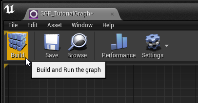
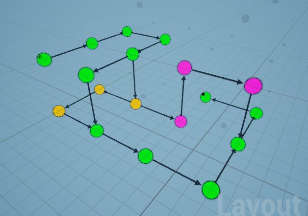
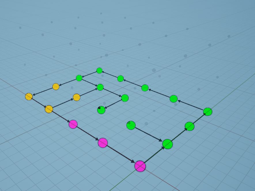
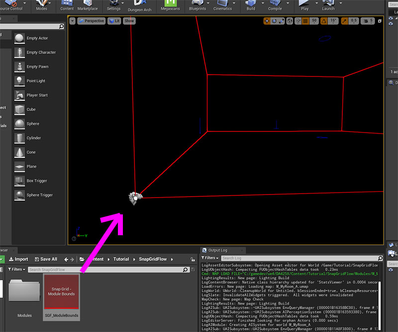
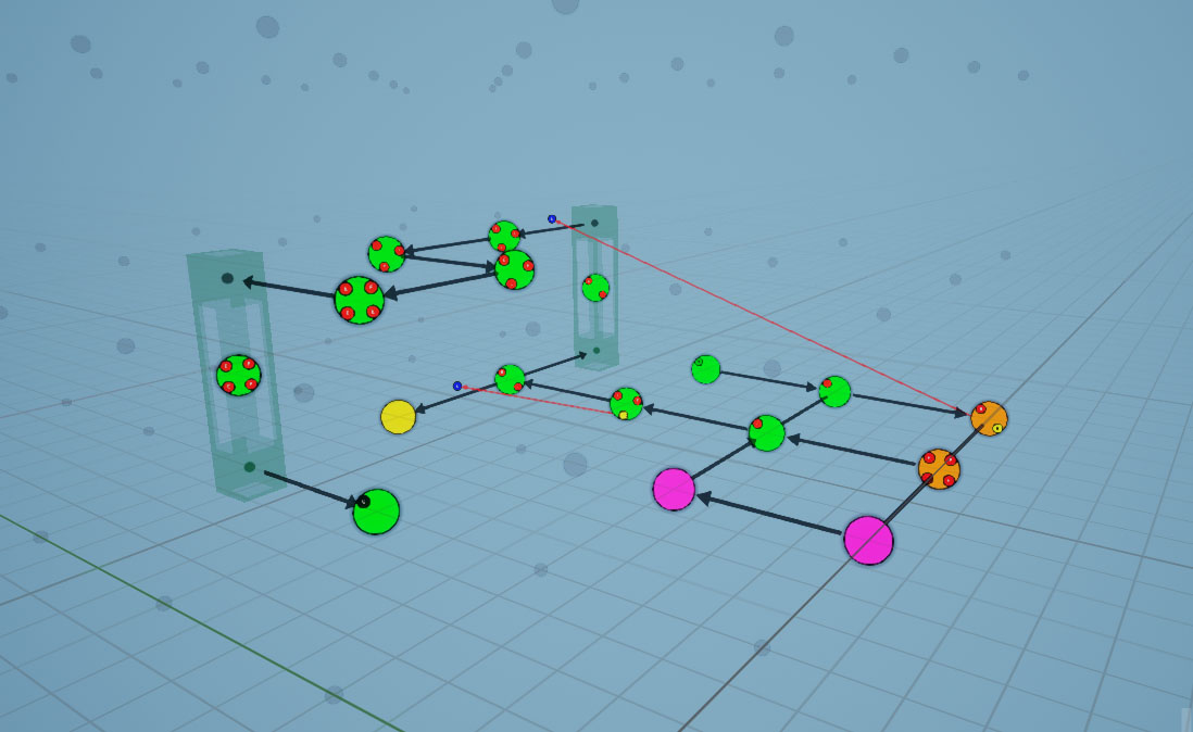
Click the Build button and have a look at the Layout Graph panel
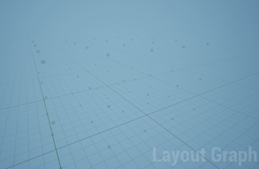
This has created a 3D grid where each dot represents a possible location for placing the nodes as we grow the dungeon graph
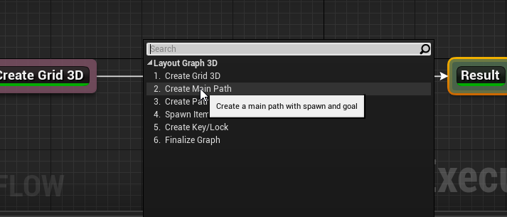
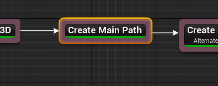
Create Main Path
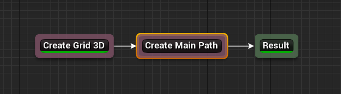
Add a Create Main Path node
Hold Alt and click on the border of the Create Grid 3D node to break the link
Connect them up as shown below and click Build
This will create a main path in the 3D grid
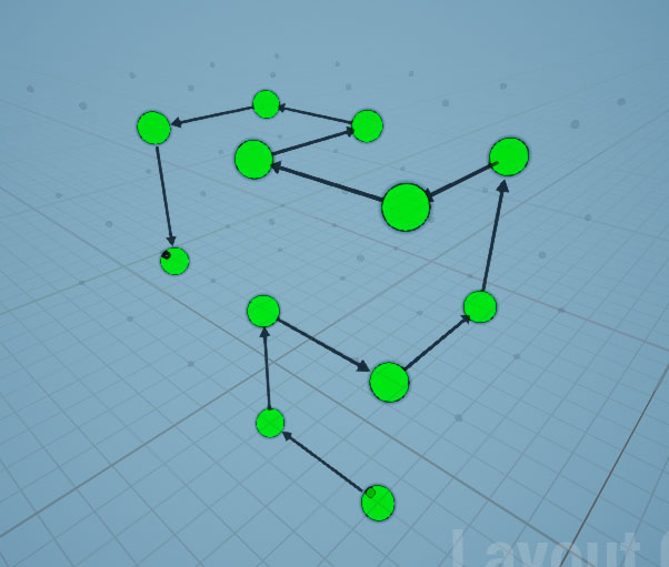
Keep hitting the Build button to get different results
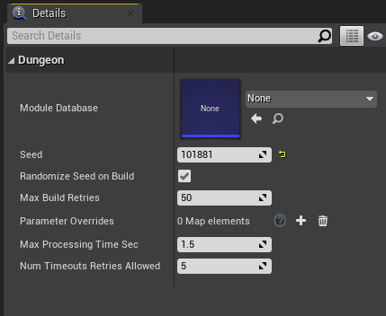
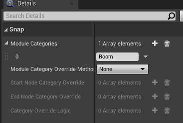
Select the Create Main Path node and inspect the properties in the Details tab
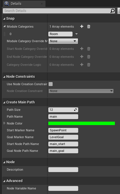
In the Module Categories array, you specify the modules to use in this path while stitching the rooms.
In the previous sections, we created a module and registered it in the Module Database with the category Room.
Leave the current default value as is, so it uses that room in the path
Leave the rest of the parameters to defaults
| Parameter | Description |
|---|---|
| Path Size | The size of the path |
| Path Name | The id used to reference this path |
| Start Marker Name | A maker will be inserted in the start node. Specify the marker name here |
| Goal Marker Name | A maker will be inserted in the last goal node. Specify the marker name here |
| Start Node Path Name | The first node in the path may have a different id (different from Path Name) |
| End Node Path Name | The last node in the path may have a different id (different from Path Name) |
| Node Color | The color of the node in the 3D preview. Used for preview visuals only |
Create Alternate Path
Add a node Create Path and connect it as below
Select the node and inspect the properties
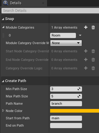
Build the graph, and you'll see a new branch (orange) emitting out of the main branch (green)
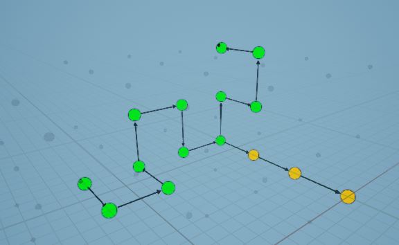
This new orange path branched out of the main (green) path because we have configured it to do so by setting the
Start from Path parameter to main
We would like to have this new path merge back into the main path
Set the End on Path parameter to main. We also want to reference this new path as alt

Control the size of the path with the Min/Max Path Size parameter
Add a description to this node


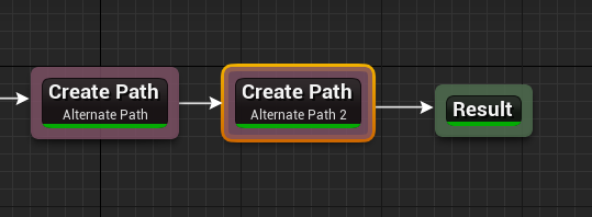
Create Another Path
We'll create another path originating from the 'alt' path and merging back into the 'main' path

Add a description to this node

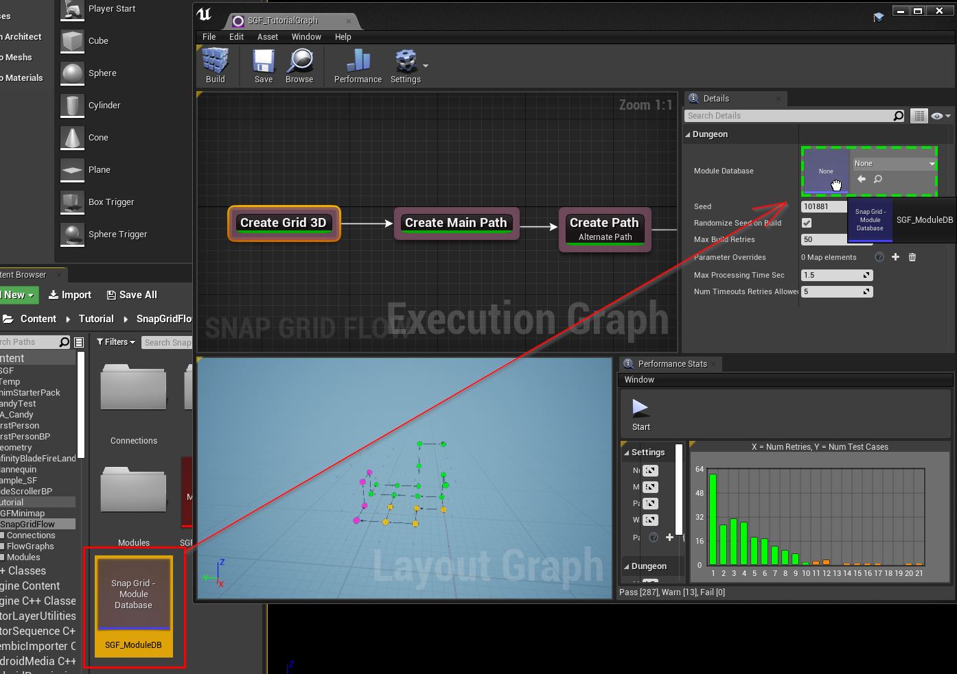
Assign Module Database
The flow editor doesn't have a module database assigned, so it doesn't really know how our modules look like
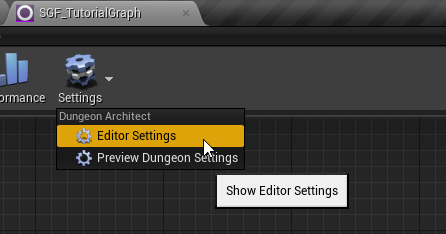
Let's assign the module database in the editor settings, so it creates a layout graph compatible with how we've set up the modules
In the toolbar, click Settings > Editor Settings
Inspect the details tab
Assign the Module Database we've created in the previous section
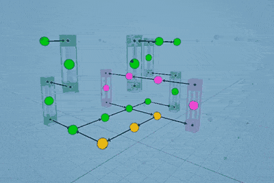
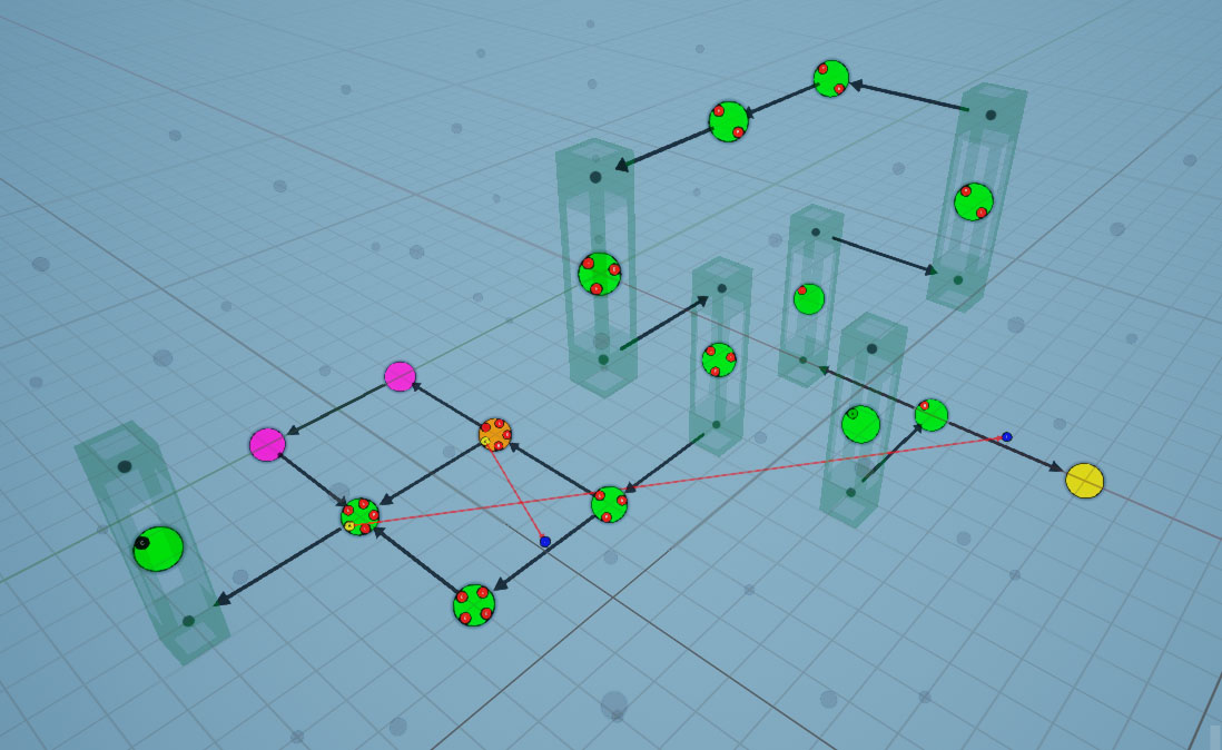
Rebuild the graph and have a look at the layout graph now
You'll notice that the flow graph is built on a single floor, which is consistent with the way we've designed our registered modules. We have designed a room which, although it goes out in the four horizontal directions, there's no way of moving up or down.
Create a Lift Module
Let's create a module that lets us move to another floor
Design Lift Module
Create a new module as we've done in the previous Modules section
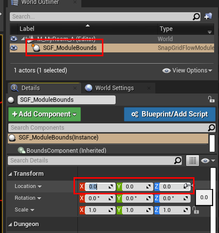
Drag drop the Module Bounds asset on to the scene and reset the transform
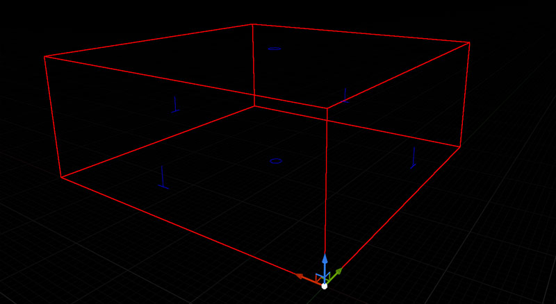
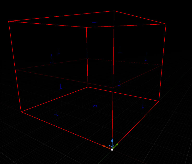
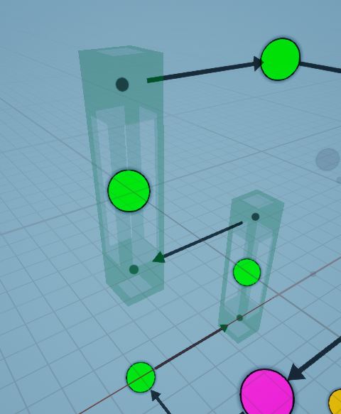
Now change the Num Chunks parameter to (1, 1, 2). This module will now span two vertical flow graph nodes

The bounds visualization will also change to aid you with the level design
Before:
After:
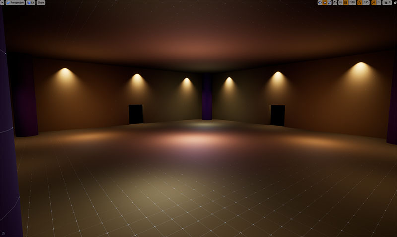
Go ahead and design your modules. Let's put in some stairs, so the player can move from the lower to the upper doors
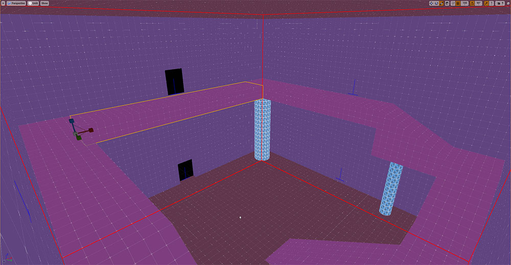
In this lift module, we have only two doors, where we come in and out of the same direction, but from different floors
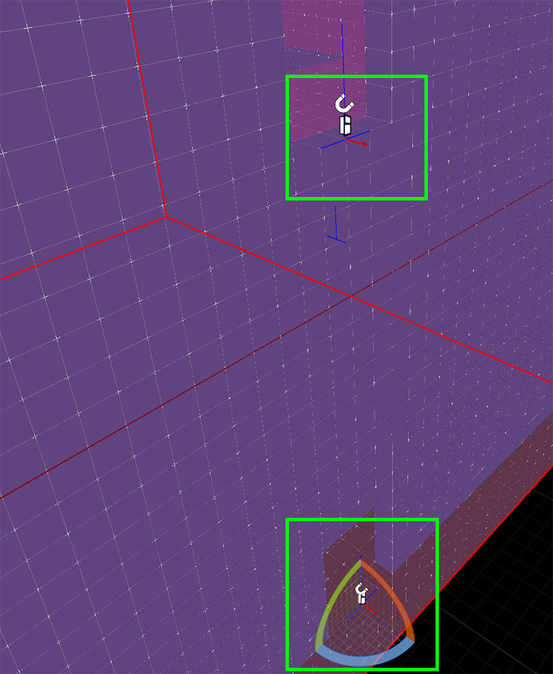
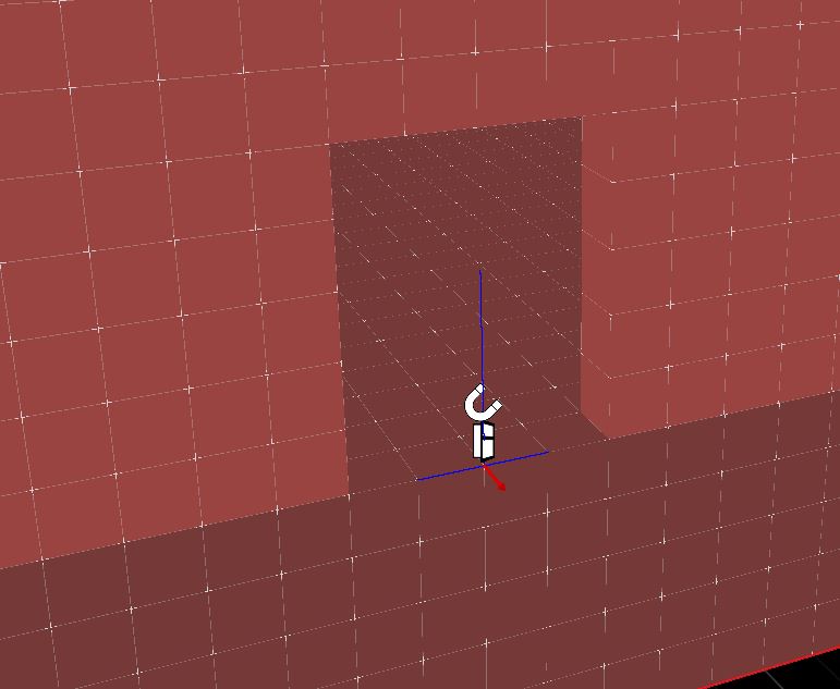
Add Connections near the door openings
Register Lift Module
Register this module in the Module database
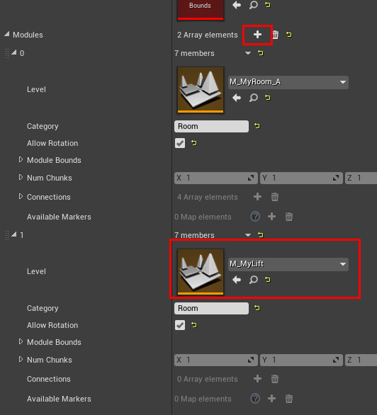
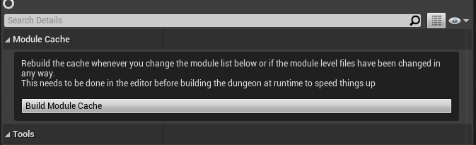
Since we've modified the module database, rebuild the module cache and save the Module DB asset
Open up our flow graph editor and reassign the Module database in the Editor Settings, as we've done previously
Click build and now, the flow graph uses the new lift module to move to other floors
Click the image to play
Notice how the links enter and exit out of the same side, since this is how we've set it up in our module design
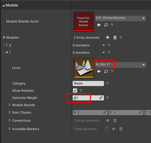
Adjust Selection Probability
We don't want the lift to show up too often. Open up the Module database and set the selection weight to 0.1
on the lift module entry
Before (with selection weight 1.0):
After (with selection weight 0.1):
Create a Goal Room
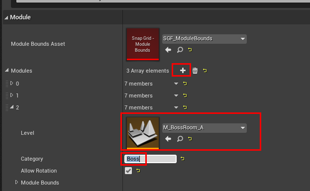
We'll create a large 2x2x2 room for the boss fight and register it under the category Boss.
Create a new Level file like before, drop in the Module Bounds asset and reset the transform
Select the Module Bounds actor in the scene and change the Num Chunks parameter to (2,2,2)

Design the level any way you like inside the red module bounds, leaving a few doors open
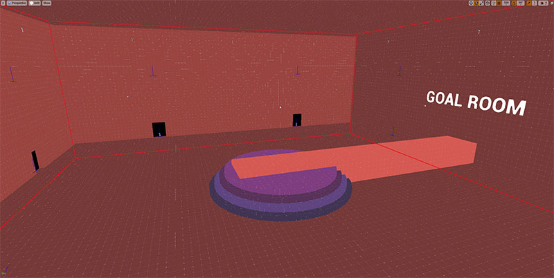
Add connectors to the door openings
Register this module in the Module Database with the category Boss

Rebuild the module database cache and save the asset
Open up the flow graph and assign the module database in the editor settings as before
Select the Create Main Path node and inspect the properties in the Details panel
Perform the following changes
- Set the
Module Category Override MethodtoStart / End Nodes - Add an entry to
End Node Category Overrideand name itBoss
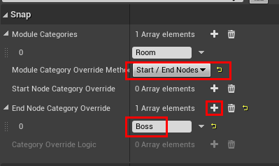
With this, we are telling the flow graph framework to choose the rooms registered under the Boss category for the
last node in the main path
Build the flow graph and have a look at the layout graph
The last node in the main path is 2x2x2 to accommodate for our goal module